

RayPowerMeter
Hardware + Software
Public Engineering Reference — AS-IS. RayPowerMeter brings four-channel RF power and SWR measurement, user calibration, and a Qt bench dashboard together in an ESP32-S3 project.
Overview
Ray Faucher (KB1SO) developed RayPowerMeter to see what was happening at several points in an amateur radio station's RF chain. The ESP32-S3 firmware reads up to four pairs of forward and reflected detector outputs and calculates power, SWR, and peak envelope power (PEP). The desktop app brings those readings together with frequency and auxiliary telemetry.
On the bench, you can compare amplifier input and output, watch SWR while tuning, and capture a detector envelope for closer inspection in the desktop scope and FFT views.
- Arrange power, SWR, frequency, and auxiliary widgets in layouts you can save and reload.
- Capture detector samples for the modulation scope and FFT views.
- Calibrate each detector path against suitable reference equipment.
Key Features
Four RF Measurement Channels
- Monitor up to four RF paths from paired forward and reflected detector outputs.
- View forward and reflected power, SWR, and peak-envelope estimates for each configured channel.
Live Telemetry
- The firmware polls enabled couplers in sequence on a nominal 20 ms telemetry loop.
- The dashboard shows connection and update age alongside readings that may retain their last values.
User Calibration
- The supplied starting tables draw on Ray's own development and test measurements. The higher-power table includes an estimated upper endpoint.
- Adjust or replace those values using suitable reference equipment for your own coupler, detector path, and operating range.
- Apply and save calibration from the desktop hardware configuration screen.
Multi-Point Calibration (Table Mode)
- Capture or enter 2–20 points per forward or reflected measurement path.
- The firmware interpolates between points. A two-point fit is also available.
- Copy points between paths as a starting point, then verify each path with your reference equipment.
Modulation Scope & Envelope FFT
- Capture one selected detector path to view the envelope in the time domain or inspect its frequency content with an FFT.
- Live power sampling can pause during a capture.
Frequency Counter
- Count the square-wave output from a compatible coupler prescaler to display RF frequency alongside power and SWR.
- The desktop frequency widget can also select optional, experimental Hamlib rig data.
Experimental Trip & Relay Control
- Explore configurable forward-power, reflected-power, and SWR trip thresholds with a relay-control output.
Aux Analog & Digital I/O
- Three auxiliary analog inputs for voltage, current, or thermistor temperature with suitable sensor circuitry.
- Four 3.3 V logic lines configurable as inputs or outputs.
Customizable Layout Widgets
- Drag-and-configure widgets tailored to your station or test bench.
- Available widgets include Power Bars, SWR panels, Mini Scopes, Aux I/O, Frequency, and Gain.
- Save multiple layouts for different operating and testing scenarios.
Qt Desktop Application
- Dockable panels, live plots, and a hardware configuration dialog for couplers, calibration, thresholds, and auxiliary I/O.
- The public build guide documents the verified Windows x64 build.
Serial & Lab Connectivity
- The standard build uses line-delimited JSON over the remote UART at 115200 baud.
- An opt-in lab build exposes the experimental Wi-Fi/HTTP interface for isolated networks.
Technology & Design
Core Platform
- The public PlatformIO build targets a compatible ESP32-S3 with 16 MiB flash.
- Check the fitted module before programming a historical board. The original drawing specifies an 8 MiB N8R2 module.
- The firmware handles detector sampling, calibration, peak calculations, and frequency counting.
Desktop Host Application
- The Qt application handles dashboards, saved JSON layouts, plots, and configuration.
- View live readings alongside separate scope and FFT captures on the bench.
RayCoupler Integration
RayPowerMeter was developed alongside the RayCoupler directional coupler family. The firmware converts forward and reflected detector voltages into power readings using the calibration for each path.
The four inputs let you compare measurements at different points in an RF chain.
- Monitor an amplifier's drive and output to estimate gain.
- Compare SWR and power readings from different antenna paths.
Use Cases
- Watch forward power, reflected power, and SWR while adjusting an antenna or tuner.
- Compare detector readings against reference equipment when calibrating a coupler.
- Inspect a modulation envelope while adjusting drive on the bench.
- Display supply voltage, current, or temperature alongside RF measurements.
Development Status
RayPowerMeter is dormant. RF StateSide published its firmware and desktop source so others can study, build, and adapt the project.
This reference is provided AS-IS. Verify measurement accuracy and operating limits for your assembly, and use independent protection for connected equipment.
Source & Documentation
The GitHub repository contains the ESP32-S3 firmware, Qt application, build files, and calibration tests. Original firmware and desktop code is licensed under LGPL-3.0-only. Controller CAD and Nextion HMI assets remain outside the public source release.
Gallery
Historical PCB render and desktop screenshots from RayPowerMeter's development.
PCB Board
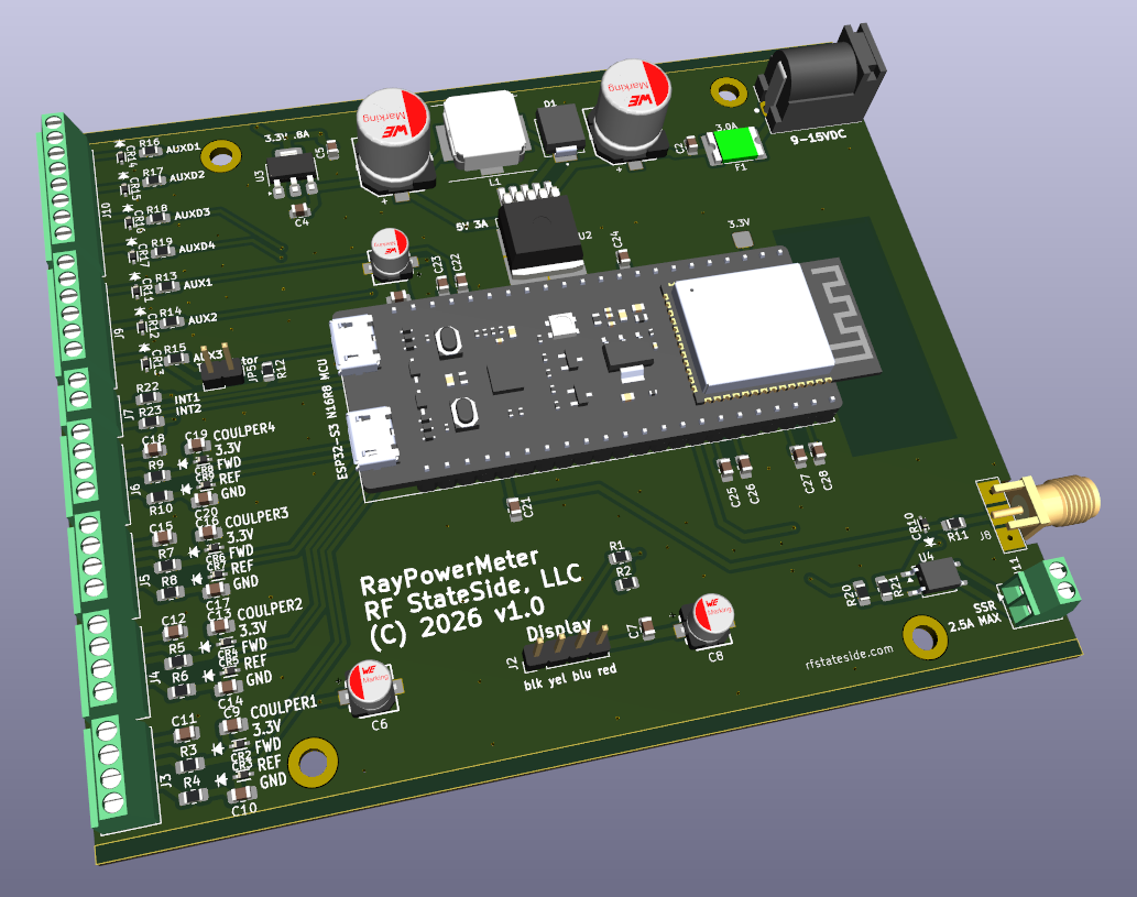
Historical 3D render of the controller board, with connections for four coupler inputs, auxiliary analog and digital I/O, a display interface, and relay control.
Desktop App — Dashboard / Live Telemetry
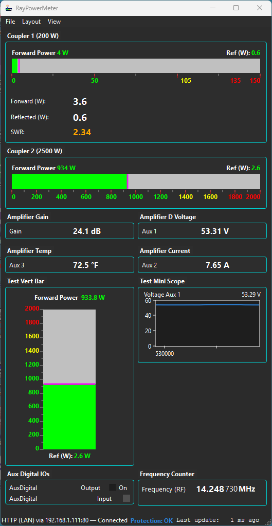
Development dashboard showing forward and reflected power, SWR, frequency, and system status.
Desktop App — Modulation Scope
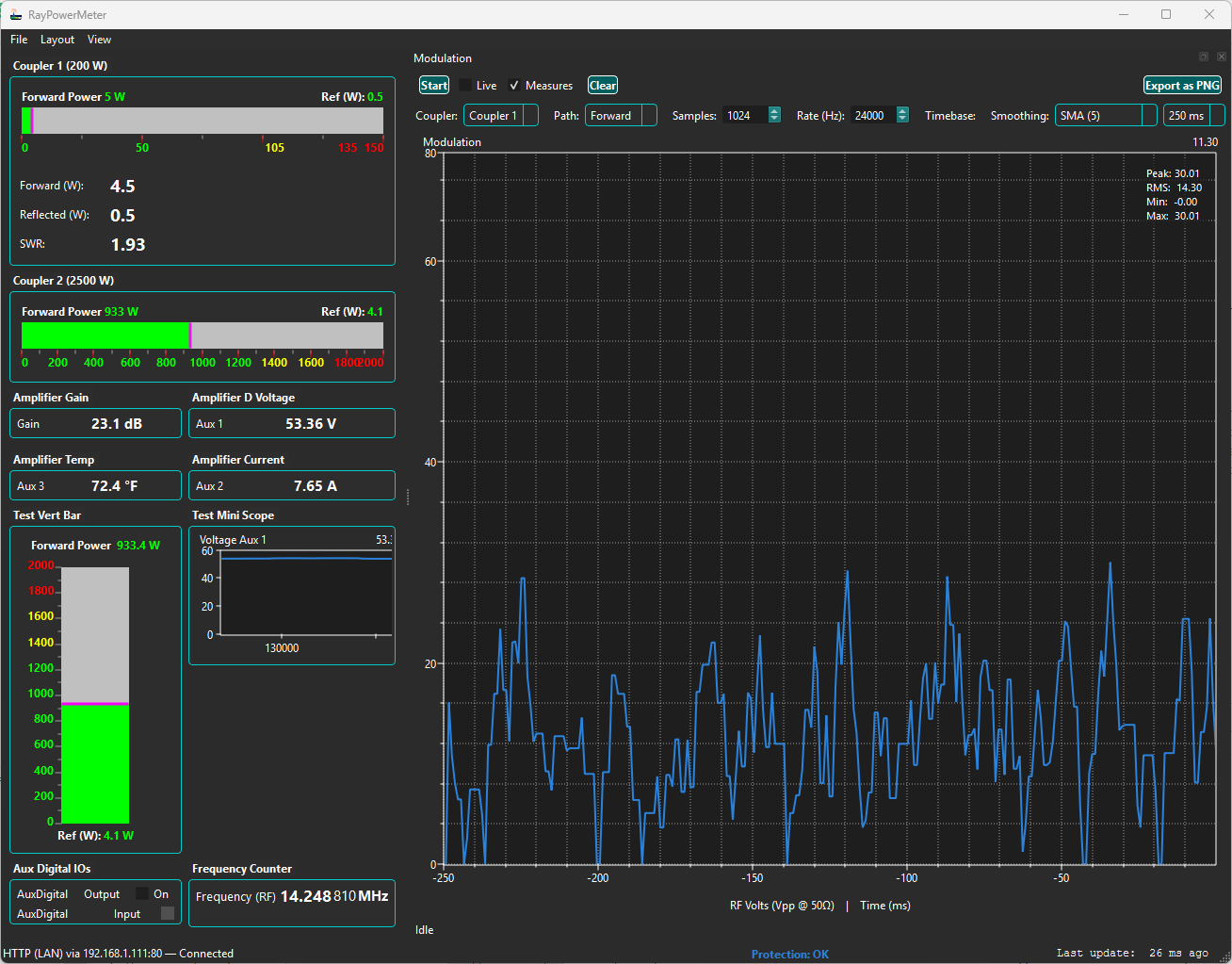
Time-domain scope showing a captured detector envelope for inspecting modulation and transients.
Desktop App — Hardware Configuration (Couplers / Aux I/O)
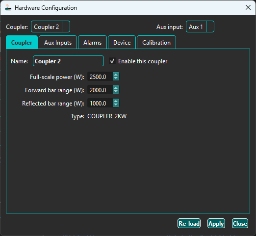
Hardware setup screen for couplers, user calibration, auxiliary sensors, and digital I/O. The firmware stores saved calibration on the device.
Discuss the Engineering Reference
Contact Ray with questions about the project's development, measurements, or use as a bench reference.